Technical information
Know-how on circuit considerations
What is an IC Evaluation?
We call the investigation of the matching between the oscillation circuit and the crystal unit an IC Evaluation.
It is necessary to design the oscillation circuit to the optimum conditions so that the advantages of the crystal unit can be fully utilized. Based on our many years of experience, we offer a service to check the characteristics of your designed oscillation circuit so that the matching between the oscillation circuit and crystal unit will be optimal.
Need for IC Evaluation
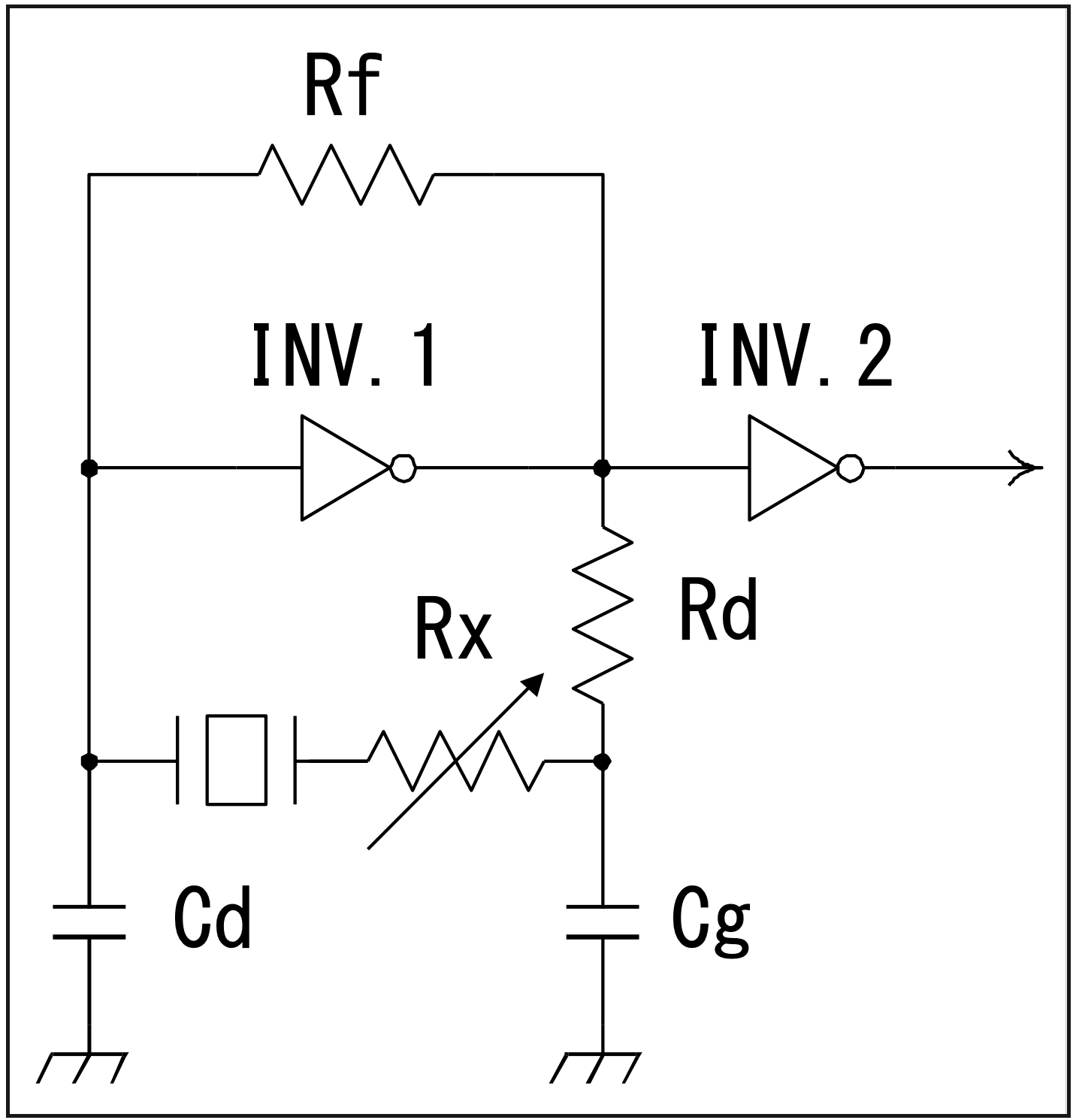
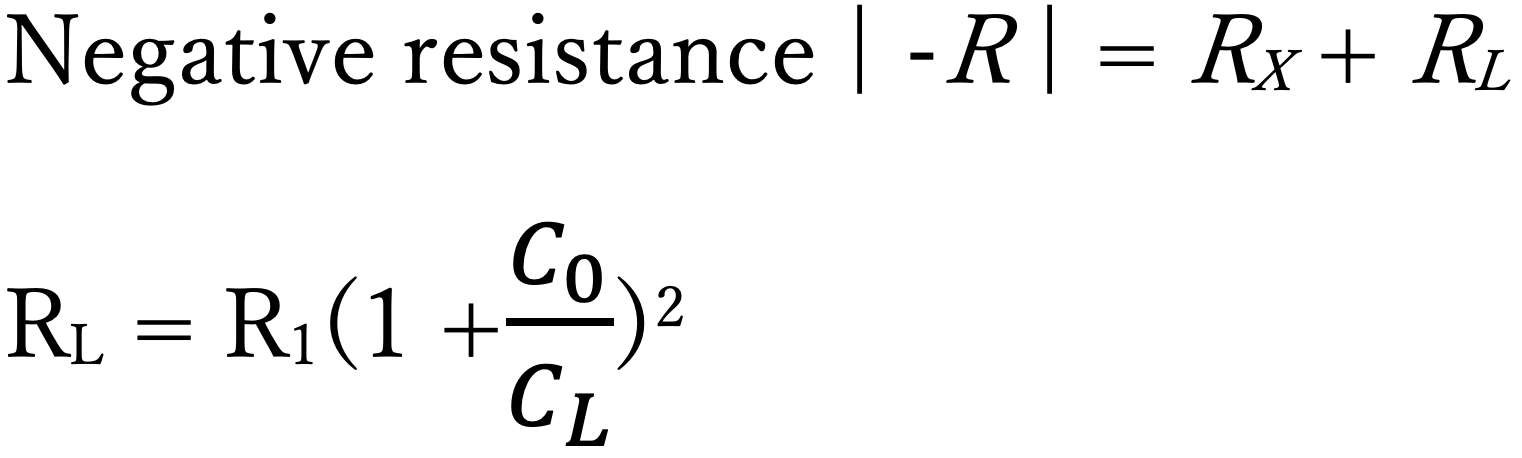
If the negative resistance of the oscillation circuit is too small, oscillation may not start (non-oscillation) upon power-on. In addition, the oscillation may become unstable, or the boot time of oscillation may be prolonged. For stable oscillation, it is necessary to ensure negative resistance.
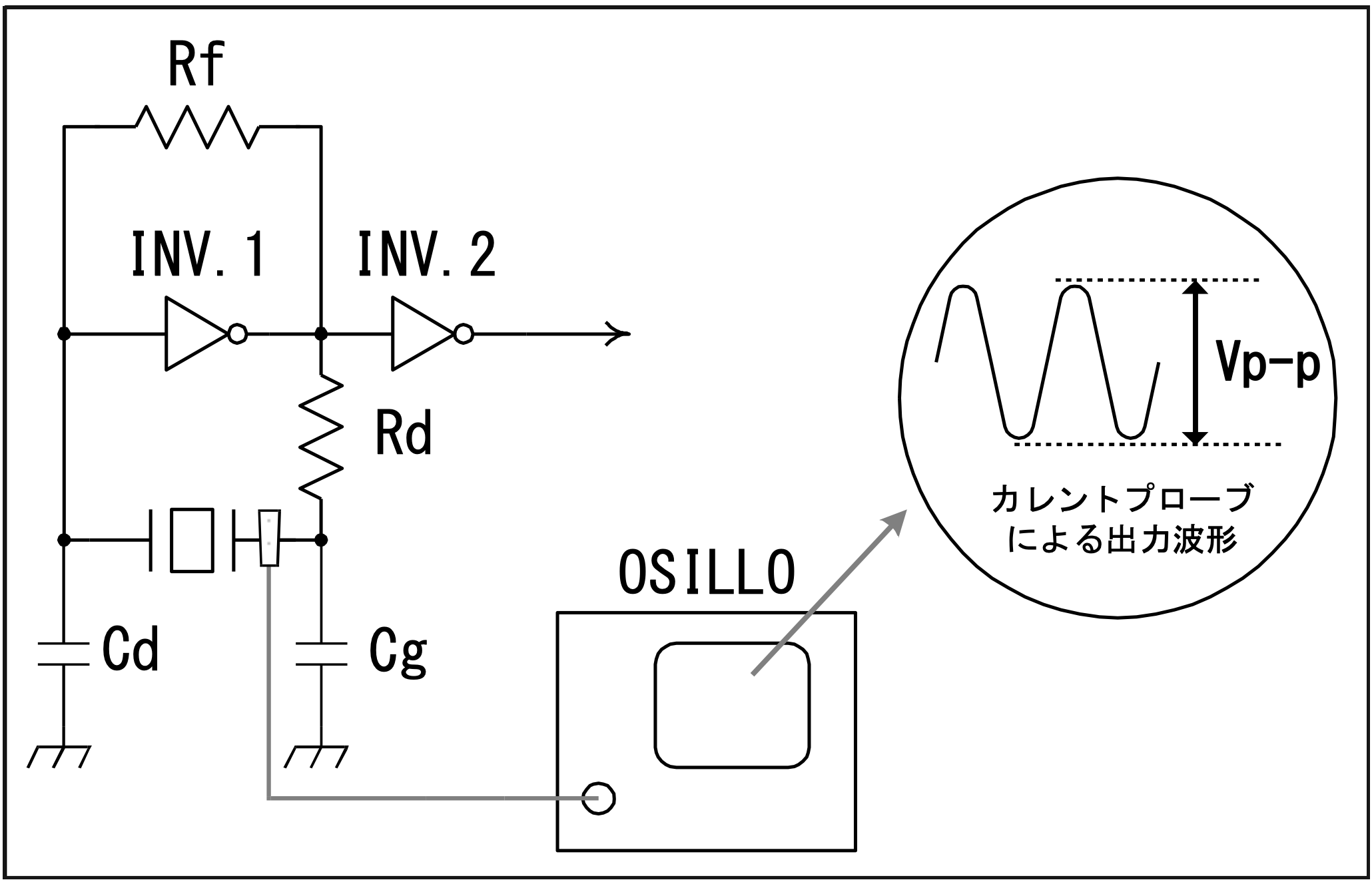
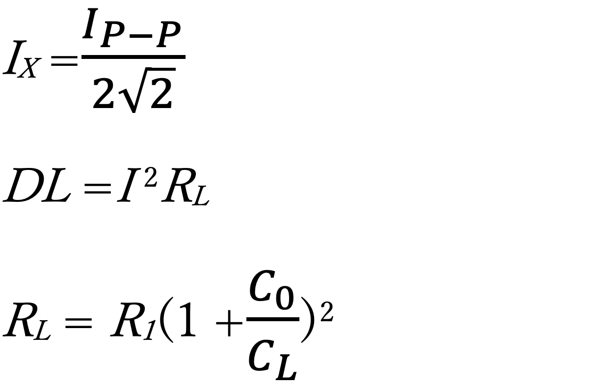
And, since crystal units oscillate mechanically, the amplitude of this oscillation (=drive level) must be limited to some suppress. Products with a small crystal shape especially need to suppress this drive level.
In addition to this, changes in the IC version or board pattern can also change the characteristics. For these reasons, it is necessary to conduct an IC Evaluation even for slight changes. It is recommended that the IC Evaluation be conducted during the prototyping phase before mass production, since it will be difficult to remedy any oscillation problems after mass production.
Example of oscillation trouble
The following is an example of oscillation trouble.
When the negative resistance of the circuit is not appropriate
- Symptom1.
- Non-oscillation (crystal unit does not oscillate)
- Symptom2.
- Non-oscillation during temperature fluctuation (Oscillation occurs at room temperature, but not when the temperature changes)
- Symptom3.
- Increase in startup time (startup time becomes longer.)
When the drive level of the circuit is not appropriate
- Symptom1.
- Abnormality of frequency-temperature characteristics
- Symptom2.
- Destruction of crystal blank (destruction of crystal blank in tuning fork products)
Mismatch between the load capacitance of the circuit and the (manufacturing) load capacitance of the crystal unit
- Symptom1.
- Deviation of oscillation frequency (significant frequency deviation from nominal frequency)
IC Evaluation research
We usually report the results within about one week after we receive the circuit board and materials (we submit an evaluation report). If it is difficult to send the circuit board because it is difficult to take the circuit board outside the company or software, etc., we can conduct an IC Evaluation at your company in person. We can also arrange for your company to come to our office for an IC Evaluation in our presence. Please contact our sales staff for details.
IC Evaluation research methodology (1)
The actual IC Evaluation research is usually conducted in the following steps
- 1. Measurement of circuit oscillation frequency.
- 2. Remove the crystal unit from the circuit board.
- 3. Measurement of negative resistance and drive level.
- 4. Measurement of single crystal unit.
- 5. Calculation of frequency deviation from the reference load capacitance.
If there is a matching problem with matching (such as unsatisfied criteria for stable oscillation), We change the circuit constants and measure. We can also measure additional data (oscillation start-up time, etc.) on customer’s request.
IC Evaluation research methodology (2)
In the IC Evaluation research, the items listed in the table below must be indicated. Please provide these instructions at the same time send the circuit board.
| Item | Reference Example (Instructions) | Remarks | |
|---|---|---|---|
| 1 | Confirmation of continuous oscillation status | Confirmed | Required |
| 2 | Power input | Red lead, From AC adapter, etc. | Required |
| 3 | Supply voltage | DC+3.3V, From AC adapter, 100V, etc. | Required |
| 4 | Operation method | Connect the PC to USB etc. | |
| 5 | Schematic, Parts layout | Including circuit constants | Required |
| 6 | Frequency measurement point | Pin number of buffer output, etc. | |
| 7 | Check item | Startup time, Oscillation waveform, etc. | |
| 8 | Frequency accuracy at room temperature | Frequency accuracy within 20ppm at room temperature, etc. | |
| 9 | Desired delivery date | Report the results by __ day of __ month. | |
| 10 | Desired date of substrate return | Return it by the end of __ month |
Oscillation stability conditions (Our recommended conditions)
We make matching decisions based on the criteria in the table below.
| Item | Cut | Standard for judgment |
|---|---|---|
| Negative resistance | AT | Equivalent series resistance is more than 5 times of the specified value, Equivalent resistance under load 3 times or more than the specified value |
| X (tuning fork) | Equivalent series resistance is more than 3 times of the specified value | |
| Drive level | AT | Below the limit drive level of the blank design value |
| X (tuning fork) | 0.5μW or less | |
| Load capacitance | AT | Minimum value is more than twice the shunt capacitance (C0) of the crystal unit |
| (The minimum load capacitance that can be supported depends on the type of crystal unit.) | ||
| X (tuning fork) | 7pF, 9pF, 12.5pF | |
Measurement methodology (1)―Oscillation frequency and load capacitance
The oscillation frequency of a circuit is measured using a probe, oscilloscope, spectrum analyzer, or frequency counter. It is desirable to use a high-resistance, low-capacitance FET probe or the like as a probe. Measure the oscillation frequency in a non-contact state by bringing the FET probe close to the crystal unit. (If there is a buffer output, it is better to use it for more accurate measurement.)

Check the oscillation frequency in the mounted state.
Measure the oscillation frequency by placing the FET probe close to the crystal unit.